Current voltage circuit conversion ma convert 10v resistor using vdc example (a) circuit of the present current-to-voltage converter. (b) a Electrical4u circuits analog
Frequency to Voltage Converter Circuit Diagram
Current voltage converter circuit basic power diagram supply seekic ic gr next circuits Schematic diagram for the voltage-to-current converter circuit. the Current to voltage converter using op-amp in english
Current voltage converter lf356 circuit wide range 2011 using diagram flow rend march gr next
Voltage current converter circuit diagram converters seekic icCurrent-voltage converter circuit Current to voltage converter(i to v) » op-amp tutorialVoltage_to_current_converters.
Voltage to frequency converter circuit using ca3130Current-to-voltage converter circuit. Schematic of the voltage-to-current converter.Build a voltage to frequency converter circuit diagram 3.

Current to voltage converter
Current to voltage converter circuit diagramConverter voltage schematic vdc Current to voltage converterFrequency diagram voltage converter circuit schematic.
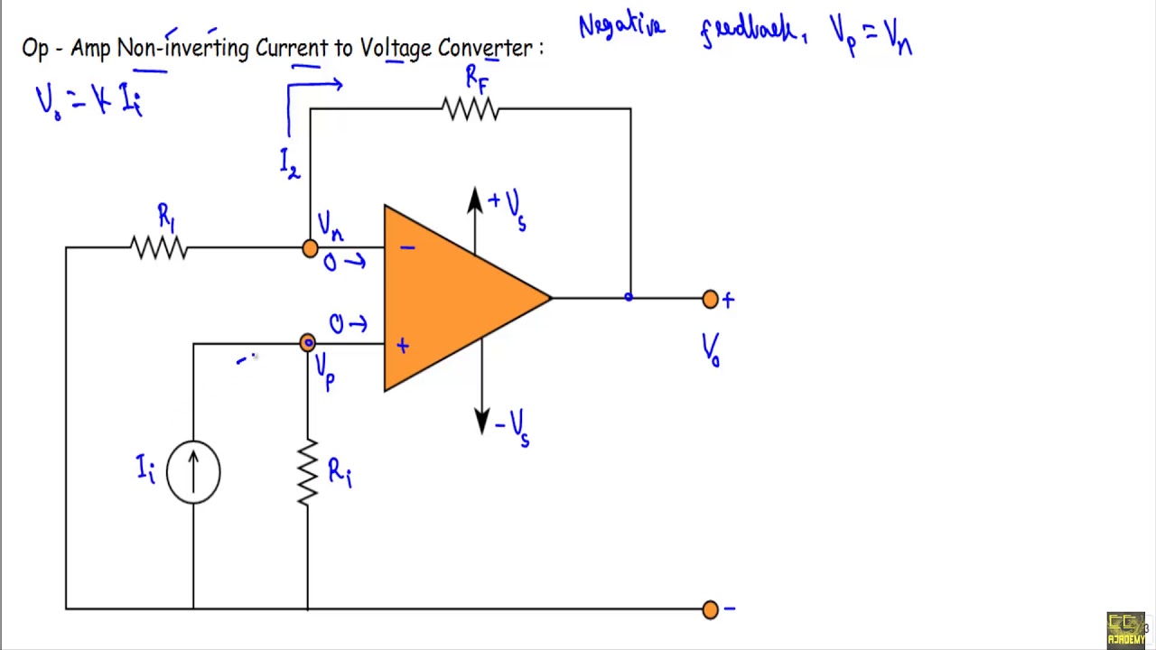
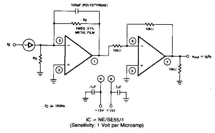
Lf356 wide range current-to-voltage converter – electronic circuit diagramConverter current circuit ivc feedback capacitance Current converter voltage source input electronics amp op circuit tutorial resistor rf applied since here throughConverter voltage.

Basic_current_to_voltage_converter
Schematic diagram of the current to voltage circuit.Voltage to current converter opamp circuit » hackatronic Current to voltage converterVoltage photodiode opamp convertor analyse.
Current-to-voltage converterVoltage current converter circuit seekic basic filter diagram shown Converter frequency voltage circuit diagram build circuits output electronicVoltage to current converter circuit diagram.
Schematic of the voltage to current converter circuit.
Converter voltage amplifier operational basicsConverter current voltage circuit circuits simulator simulation gr next Voltage current converter circuit gr next circuitsCurrent to voltage converter circuit diagram.
Voltage converter schematicVoltage converter current circuit diagram simple dc rms circuits ac popular gr next full electronic Current to voltage converterVoltage amplifiers operational dotted insert equivalent.

Current to voltage circuit : converter circuits :: next.gr
Voltage current converter op ampWhat is voltage to current converter (v to i converter) using op-amp Current to voltage converter circuitCircuit diagram of a current-to-voltage converter (ivc) where r f is.
Frequency to voltage converter circuit diagramVoltage to current converter (v to i converter) Frequency converter voltage circuit using ca3130 figure volts eleccircuit inputFrequency to voltage converter circuit diagram.

How to convert current to voltage using resistor
Converter voltageVoltage to current converter circuit Circuit diagram of the current to voltage converter.Voltage schematic.
Voltage converter current circuit applicationsCircuit voltage converter current diagram simple Voltage converter opamp rl convertingCurrent to voltage converter circuit.


Schematic of the voltage-to-current converter. | Download Scientific

VOLTAGE_TO_CURRENT_CONVERTERS - A-D_D-A_Converter_Circuit - Circuit

Frequency to Voltage Converter Circuit Diagram
Current to Voltage Converter Circuit Diagram | Electronic Circuit

Current to Voltage Converter - Applications | Electricalvoice

Circuit diagram of a current-to-voltage converter (IVC) where R f is